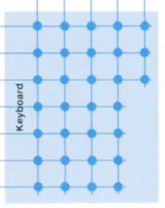
Scanning the calculator keyboard to see if a key has been pressed, works pretty much the same on a HP-21 as all the other calculators. This is the process .
The keyboard is wired up in rows and columns, like:

There are three rows of five keys at the top and four rows of four keys at the bottom.
The calculator keys are positioned over switches that connect a row to a column. The calculator sends a signal down each row in turn and looks for a signal on any of the columns. If it sees one, it can tell that a key has been pressed and which one it is.
The rows are assigned values like 0x10, 0x20, etc. The columns are also assigned values and these are chosen to not conflict with the row ones, eg 0, 1, 2, ….
For a HP-21, the row values from top to bottom are: 0xb0, 0x40, 0xd0, 0x60, 0xa0, 0x70 and 0x90.
The column values (left to right) are: 4, 3, 2, 1, 0.
As you can see from the diagram above, where there are only four switch positions on a row (the bottom four rows), the keys are wired up to the leftmost columns. This means, for example, the HP-21 DSP key has a scan code of (row) 0x90 + (fourth column from the left) 1 = 0x91; not 0x90.
The ENTER key complicates things on the third row from the top. You can see in the diagram that there are five switch positions on that row. You can also see from looking at the calculator that there are only four keys there. The ENTER key is wider than other ones and it occupies the space over two switches (the left most and the second one on the row). As a result, the second, third and fourth keys on the row (CHS, EEX, CLx) are over the third, fourth and fifth switches and appear as third, fourth and fifth column keys. Just think of the twice as wide ENTER key as being two keys and it all makes sense.
If the ENTER key is over two switches, what happens when it get pressed? The answer is simple: the row 3 column 1 switch. I don’t know how it does it. I’m pretty sure there’s two switches under it. Perhaps only the left hand one is connected to anything. That’d seem to be the best way of achieving mechanical stability and simplicity, and also the electrical outcome.
The scan codes are:
| Row | Col | Key | Scancode |
| 1 | 1 | 1/X | 0xb4 |
| 1 | 2 | SIN | 0xb3 |
| 1 | 3 | COS | 0xb2 |
| 1 | 4 | TAN | 0xb1 |
| 1 | 5 | g | 0xb0 |
| 2 | 1 | x<->y | 0x44 |
| 2 | 2 | Rv | 0x43 |
| 2 | 3 | e^x | 0x42 |
| 2 | 4 | STO | 0x41 |
| 2 | 5 | RCL | 0x40 |
| 3 | 1 | ENTER | 0xd4 |
| 3 | 3 | CHS | 0xd2 |
| 3 | 4 | EEX | 0xd1 |
| 3 | 5 | CLx | 0xd0 |
| 4 | 1 | – | 0x64 |
| 4 | 2 | 7 | 0x63 |
| 4 | 3 | 8 | 0x62 |
| 4 | 4 | 9 | 0x61 |
| 5 | 1 | + | 0xa4 |
| 5 | 2 | 4 | 0xa3 |
| 5 | 3 | 5 | 0xa2 |
| 5 | 4 | 6 | 0xa1 |
| 6 | 1 | x | 0x74 |
| 6 | 2 | 1 | 0x73 |
| 6 | 3 | 2 | 0x72 |
| 6 | 4 | 3 | 0x71 |
| 7 | 1 | / | 0x94 |
| 7 | 2 | 0 | 0x93 |
| 7 | 3 | . | 0x92 |
| 7 | 4 | DSP | 0x91 |
This is part of the HP-21 topic.


