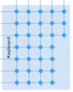
A calculator keyboard gets scanned to see which, if any, key has been pressed.
It is a fairly simple process. The calculator activates each keyboard row in turn, and checks to see if a signal appears in any of the columns. Each key connects a different row to a different column. It looks like this:

(from HP Journal, 1975-11, page 9)
There’s up to 5 keys across, and there’s 7 rows of keys.
The ENTER key is always the first key (LHS) on the third row (from the top). It is a wide key, that occupies two positions on the grid. I’m not sure of the exact mechanics, but it only presses the first switch. The other three keys on the same row appear in the third, fourth and fifth columns.
The row values (top to bottom) are: 0xb0, 0x40, 0xd0, 0x60, 0xa0, 0x70 and 0x90.
The column values (L->R) are: 3, 2, 1, 0 and 4.
This means the ENTER key causes a scan code of (row 3 + col 1) 0xd0 + 3 or 0xd3.
In the microcode, when the calculator does a “keys -> a” instruction and the ENTER key has been pressed, 0xd appears in A[2] and 0x3 appears in A[1].
This means the scancodes are:
| Row | Col | Key | Scancode |
| 1 | 1 | SST | 0xb3 |
| 1 | 2 | GSB | 0xb2 |
| 1 | 3 | GTO | 0xb1 |
| 1 | 4 | f | 0xb0 |
| 1 | 5 | g | 0xb4 |
| 2 | 1 | x<->y | 0x43 |
| 2 | 2 | Rv | 0x42 |
| 2 | 3 | STO | 0x41 |
| 2 | 4 | RCL | 0x40 |
| 2 | 5 | SUM | 0x44 |
| 3 | 1 | ENTER | 0xd3 |
| 3 | 3 | CHS | 0xd1 |
| 3 | 4 | EEX | 0xd0 |
| 3 | 5 | CLx | 0xd4 |
| 4 | 1 | – | 0x63 |
| 4 | 2 | 7 | 0x62 |
| 4 | 3 | 8 | 0x61 |
| 4 | 4 | 9 | 0x60 |
| 5 | 1 | + | 0xa3 |
| 5 | 2 | 4 | 0xa2 |
| 5 | 3 | 5 | 0xa1 |
| 5 | 4 | 6 | 0xa0 |
| 6 | 1 | x | 0x73 |
| 6 | 2 | 1 | 0x72 |
| 6 | 3 | 2 | 0x71 |
| 6 | 4 | 3 | 0x70 |
| 7 | 1 | / | 0x93 |
| 7 | 2 | 0 | 0x92 |
| 7 | 3 | . | 0x91 |
| 7 | 4 | R/S | 0x90 |
These are the same scancodes for the button positions, as those used for the HP25.
This is part of the HP-29 topic.


